

 Tiếng Việt
 CAMERA TRICKS
 IT TRICKS


 APPLICATION SOFTWARE
 VIDEOS

 TOOL
TOOL


 SOLUTION

 TECH NEWS
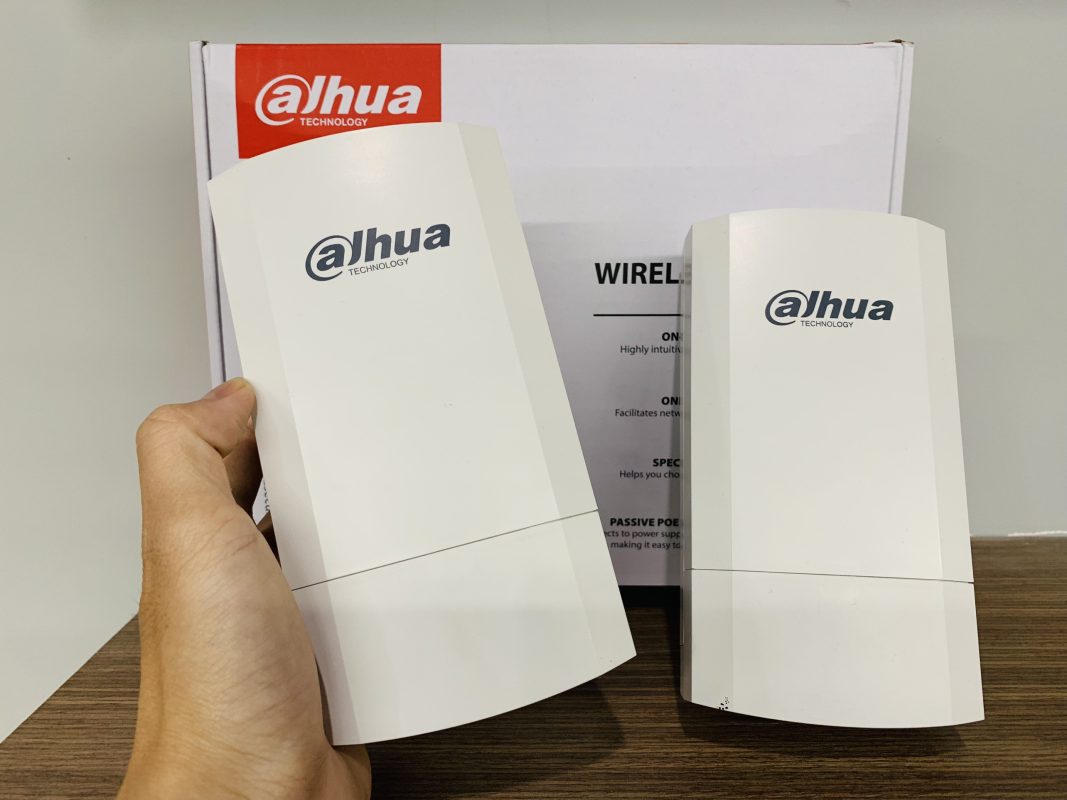
Dahua Wireless Bridge (CPE) transmitter is specially designed for wireless data transmission, such as HD video, in elevators, workshops, etc. It adopts IEEE 802.11n technology and operates in the 2.4 GHz frequency band, delivering a wireless data transfer rate of up to 300 Mbps. Two built-in 6 dBi high-power directional antennas produce a strong signal and have a wide coverage.
Highly reliable, OSD (On-Screen Display) and one-tap pairing, makes it easy to install and is a great choice for use in elevators, factories, etc.
Contents
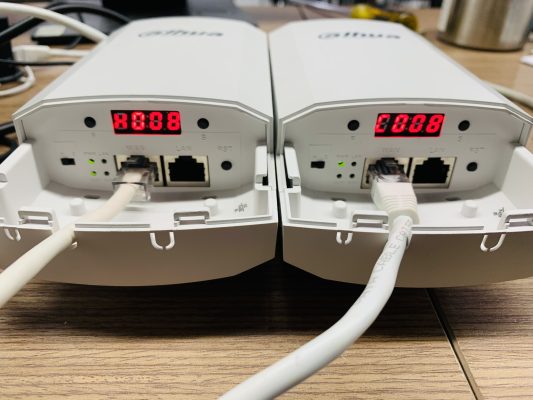
I. Overview
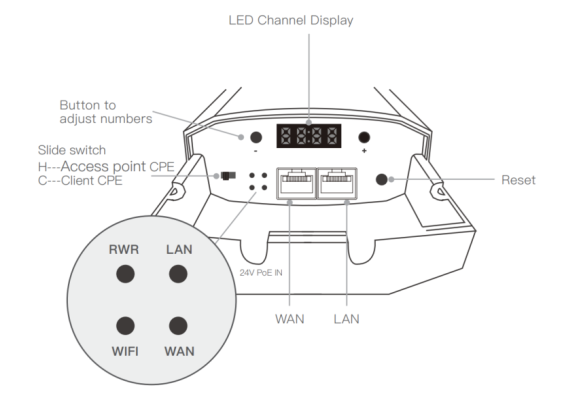
- Wifi: Light status Off --> Pairing failed – Continuous green --> Pairing successfully
- LAN: Light status Off --> No connection – Continuous green --> Connection activated
- WAN: Light status Off --> No connection – Continuous green --> Connection activated
- SYS: Light Status: Off --> Power Off – Dark Blue --> Working
II. Installation
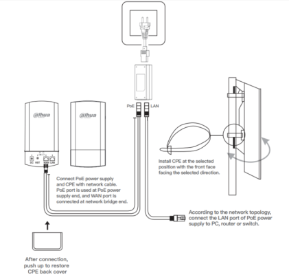
- Install the CPE at the selected location with the front facing the selected direction.
- Connect PoE and CPE power supplies using a network cable. The PoE port is used at the PoE power supply end, and the WAN port is connected at the network bridge end
- According to the network topology, the LAN port connection of the PoE power feeds to a PC, router or switch.
- Once connected, push up to restore the CPE back cover
III. POE Connection
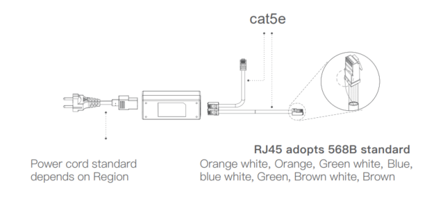
- Power cord standards depending on the region
- RJ45 adopts 568B standard Orange White, Orange, Blue White, Blue, Blue White, Green, Brown White, Brown
- Default configuration:
- Default IP: Access point: 192.168.1.35/24 – Client: 192.168.1.36/24
- Usernamer: admin
- Password: admin
IV. Quick Setup
1. Configure Access point-Client CPE
-
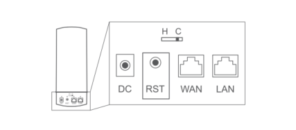
- Select a CPE that turns the slide switch to position H, setting it as an Access point
- Select the other CPE, flip the slide switch to position C, set it to Client.
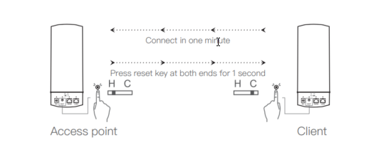
2. Connect the device
-
- Press the Reset key on the Access point for 1 second and the Reset key on the client device for 1 second. To proceed with establishing a new connection
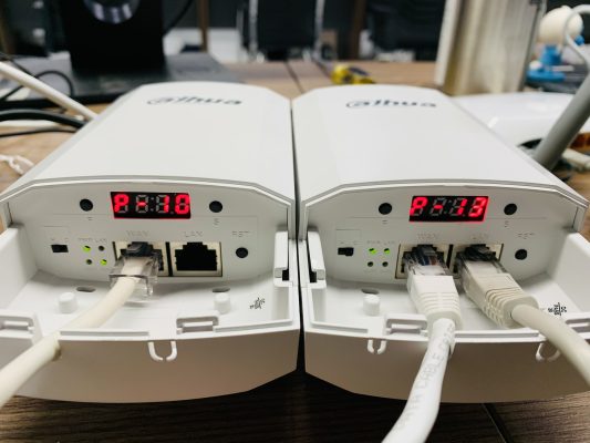
3. Install Digital Display Bridging
-
- Configure Access point CPE
-
- Configuring Client CPE
Select the device as the Client, press the F key to flash “H” or “C”, then press the S key to change it to “C”. After 5 seconds, the device will automatically save to client mode and reboot.

-
- Channel modifications
On the Access point, press the F key twice to select the channel, and then press the S key to modify the channel. After 5 seconds, the device will automatically save the new channel and reboot.
*Simply modify the channel of the Access point bridge and the channel of the client device will automatically match the channel of the Access point.

-
- IP modification
Press the F key three times to select the IP flash, then press the S key to modify. After 5 seconds, the device will automatically save the new IP address and reboot.

V. Configuration using the browser WEB
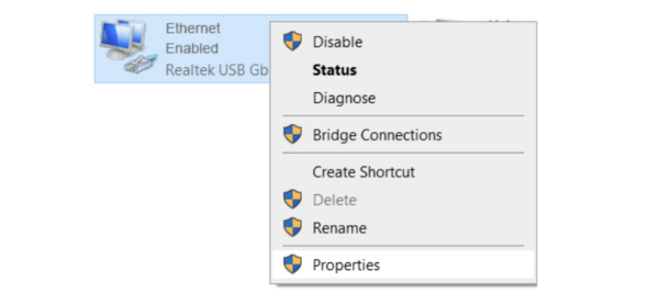
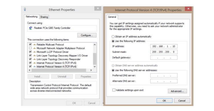
1.Install on PC
Wired connection method: The PC used for installation needs to set the IP address of the wired Ethernet to 192.168.1 X (value of X is 11-200), the same network range as the CPE
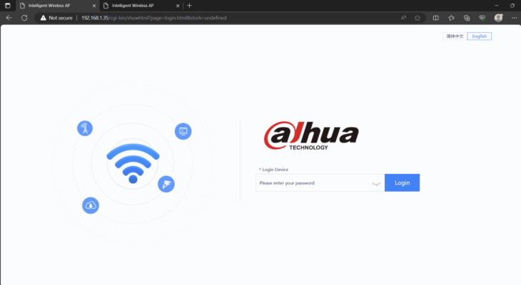
2. Open Google Chrome, Enter the default IP address of Access Point 192.168.1.35. On the page that appears, enter the password: admin, then click Login to enter the homepage
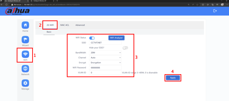
3. Go to Wifi --> 2G Wifi --> Check enalble Wifi Status and enter the parameters for Access Point
- SSID: CCTVIT.NET (Access Point name)
- Hide your SSID: Access Point name hiding feature
- BandWidth: 20M (bandwidth)
- Channel: Auto (wifi channel selection – you can leave auto or select wifi channels in areas you rarely use through WiFI Analyzer feature)
- Encrypt: Encryption (confidential mode)
- Wifi Password: 66666666 is the default password of Access Point, you can change it according to the purpose of use
- VLAN ID: 0 – you can specify VLANs from the router
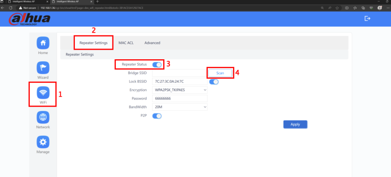
4. Log in to the client device with the default IP address 192.168.1.36. On the page that appears, enter the password: admin, then click Login. Then select Wifi --> Repeater Settings --> Check Enable Repeater Satus --> Scan
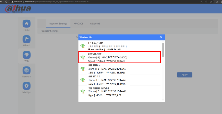
5.Select the created Access Point name
6. Enter the password of the created Access Point, then click Apply to connect
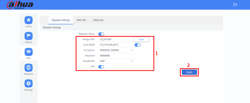
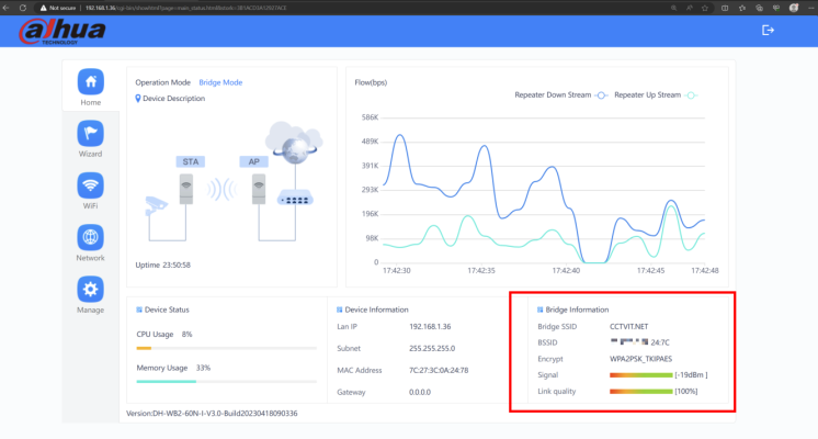
7. Status successfully connected to Access Point
Thank you for following cctvit.net’s article!